A modern day solution for creating reciprocated ornamental turned
pieces
using the Legacy Ornamental Mill
by Tim Krause
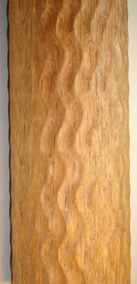
I developed the TK Reciprocator for duplicating a technique that is used in ornamental turning. The final effect is sine wave patterns carved into cylinders. By making three different adjustments, thousands of different wave patterns can be created.
I was inspired by the original device invention created by an amateur for the Holtzapffel Ornamental Lathe. Mr. G.C. Atkinson named his version "The Atkinson Reciprocator". The name fully describes its function. In the spirit of amateur inventors such as myself, I named my creation built for the Legacy Ornamental mill the, "TK Reciprocator". The simpler name of, "The Wave Attachment", is now what it's being called on Google's Legacy Ornamental Mill group.
During the same time, Curt George also made a wave attachment of his own. You can search the archives for his design. It is much more robust than my version.
The goal of the reciprocator is simple. Convert a rotating spindle motion to a back and forth motion. When combined with the spiral capabilities of the Legacy Ornamental Mill, we achieve the same antique sine wave patterns using modern tools.
My invention is different from the original reciprocator attachment developed by Atkinson. His design had multiple holes on an arm to adjust the amplitude of the wave. In my version, I use a slide to create an infinite variety of heights available in the wave.
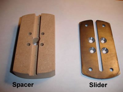
Installation is simple, and the parts can be left on the machine full time if desired. First the slider and spacer are attached to the standard duplex gear provided by Legacy. Four longer screws are included. The screws are intentionally left long to account for varying thickness of the duplex gear. Do not over tighten the screws. Once the screws are installed, file them flush or slightly under the surface of the bronze bushing to prevent interference with the sliding arm.
The spacer and slider look like this:
Next, using the following components, install the connecting rod and bushing to the slider. The allen screw and small washer are not shown.
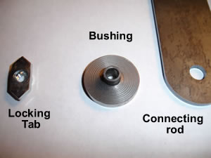
The connecting rod is attached to the slider with the threaded locking tab inside the groove of the slider, and the connecting rod bushing on the outside of the slider. The connecting rod should move freely on the bushing. The opposite end of the connecting rod has a pvc block with a split pin and a magnet installed in the face. The pin fits inside a hole in the index plate, and the magnet holds the connecting rod in place.
The slider assembly should look like this when completed. The duplex gear is not shown:
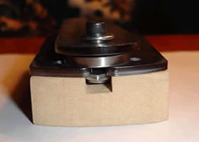
The connecting rod should now be hanging down from the slider assembly.
Installation is now complete.
Start by setting the pitch of the X-axis screw by choosing the appropriate Legacy spiral gear. 4"-6" of pitch is a good starting point.
See the notes at the end of the page for more information.
Loosen the allen screw and slide the bushing and connecting rod to the desired offset. You can choose either side of the center of the duplex gear. Lock down the allen screw. Do not over tighten the screw. A little offset adjustment goes a long ways. Start with 1/8" to 1/4" to see what happens. The 2" offset is really radical.
*** Note, See the notes at the end of the page for more information on the different effects of locating the bushing to the left or right of center later.***
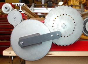
Next, place the split pin on the connecting rod in a hole on the index plate. This will be used to lock the spindle to the duplex gear, and create the back and forth rocking motion. It does not matter which hole you start in. I usually use a hole that is in the 6:30 or straight down location for easy reference. In the picture below, you can see the slider adjusted to the furthest extreme, and the spindle is just about ready to change direction.
***Note, the plastic thumb screw that holds the main drive gear to the spindle might be need to be replaced with a standard bolt for clearance purposes. Please check your installation for any problems. ***
Now, adjust the duplex gear arm so that the X-axis gear is engaged with the directional gear, and the large outside duplex gear is engaged with the directional gear. Adjust the duplex gear arm so that the inner smaller gear of the duplex gear is DISENGAGED from the main drive gear. As with all things Legacy, the gear train should be loose enough to freely turn, but not so loose that the gears will disengage during machining. The duplex gear may be adjusted nearer or farther from the main gear depending on the amount of offset on the slider. Check for binding when the bushing on the slider is in the 8:40 position and the connecting rod is located on the index plate. It should be obvious once you install the connecting rod for the first time.
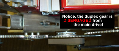
NOTE ***As a final check, the gear train when activated should now make the spindle rock back and forth. If not, check for binding, and that all gears are engaged, and that the duplex inner gear is not engaged to the main gear. ***
With the reciprocator setup complete, locate the router carriage to the start of your piece, and lock the split nut on the X-axis in place. Be careful that the router will not interfere with anything before turning on the X-Axis motor and router. You might even want to verify the direction of the screw before locking the split nut. It would be better to be safe than sorry!
Assuming you have a X-axis motor, turn the motor on to advance the router carriage. The spindle will be oscillating back and forth as the carriage travels from the head stock to the tail stock. I have been cutting an 1/8" depth of material at a time, and the action seems effortless. Once the first cut is made, lift the router, and drive the router carriage back to your starting point. Do not remove the pin, or unlock the split nut to perform this action. Run your next cutting path the same as before. Repeat as often as is needed to cut your desired depth.
With the first row cut, drive the router carriage back to your starting point. Choose your next index on the index gear. If you are using a 24 start wave pattern, simply go to the next hole on your standard Legacy index plate. If you want a 12 start wave, skip a hole etc. Repeat the cutting process until your piece is completed.
As you will see in practice, this is a safe and simple procedure. The magnet allows a quick change to the next wave index. There is flexibility in the adjustments with no math required.
Note, there is a method to save time and avoiding having to drive the router back to the starting position. It involves noting the starting point of the router and the ruler, and the gear teeth location. You can loosen the split nut and return your router carriage to the starting point. Then align the teeth so they are in the same starting relation, and make your next cut. This is a little more advanced, but a real time saver.
The wave attachment creates 4 waves per pitch length when used with the standard Legacy duplex gear. Knowing this bit of information will help you determine the router bit width and depth of cut.
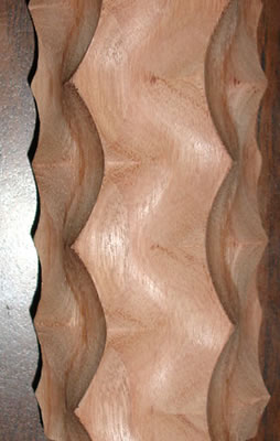
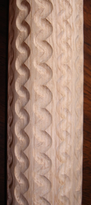
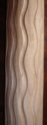
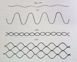
A DNA twist such as figure 178 in the picture below, can be made by placing the bushing on the slider at the opposite side of the center of the duplex gear and at same offset distance. I have not cut a part yet to show this, but it is completely plausible. Below is only a few examples of what can be accomplished.
Another fun thing to try is to start with a standard narrow wave, and advance the router carriage on the screw 1/4" for each new wave start. That should create a bit of a rolling wave. I think this would be impressive on a 24 start using a 1/4" cove bit on a 3" diameter piece.
Since this is a work in progress, who knows what enhancements and discoveries will be made. I think the possibilities are close to endless.
Connecting rod pops off during machining: If the magnet is not strong enough to hold on to the main index gear, here are a few suggestions. First check for binding. Next check for alignment of the gears. The spacer widths for the slider or connecting rod might need to be adjusted. Check the adjustment on the duplex arm. Are you taking light machining passes? Is it a telephone pole? If all of those fail, my original design used a bolt arrangement that allows things to turn freely. A quick release pin has been suggested, but I have not source the part yet. Ultimately, contact me so the appropriate design changes can be made.
Connecting rod seems too short: First check that the duplex arm is adjusted correctly. The rod has been tested to all extremes and stock Legacy gears.
Main Drive Gear is getting scratched: Unfortunately this is going to happen. The cause is the duplex gear is allowing the gear to flop around a bit under the strain of changing directions. This causes the duplex gear to rub the main drive gear occasionally. A future design includes the proper support of the duplex gear on the duplex adjusting arm with an additional bearing, or possibly a bearing included in the slider spacer. This is still under development.
X-axis motor stalls: This can be caused by the gears being set too tight, or the gear used for the pitch might be to large. My motor is slightly larger than Legacy's motor, so I would like feedback if this is happening. The use of the stock hand crank could be a solution to the problem. The reciprocator has only been tested on small stock. It is not intended to be used to turn large pieces. The limitation in size is unknown at this point. Please send feed back if a failure occurs due to size.
Peaks of the wave are not crisp: If you notice that the wave peaks seem a little square for your tastes, you can add a light 6" spring to the main index gear that attaches to the right side of the legacy. Place one end in a index hole, and attach the other end to the legacy. This removes any amount of slop from the connecting rod assembly. Too strong of a spring can cause binding. It's debatable if this spring is needed for most patterns.
Everything just blew apart!: The pictures on this web page provide enough information for you to make your own version of the TK Reciprocator. There are no plans available at this moment. If the use of the reciprocator breaks anything, I cannot be held liable. 1000 apologies, but that's the extent of my guarantee. The information provided on this page should be considered entertainment only. It works for me, but your mileage may vary. Can I make this any clearer?
Legacy has no idea what I'm asking for: The TK Reciprocator is not available from Legacy Woodworking. I have a few prototypes available if you are interested in seeing if and how this can work for you. It is offered as is. Contact me for price and availability.
Disclaimer: I am not associated with Legacy Woodworking or Phantom Engineering. My idea is not supported or discouraged by the inventors of the Legacy Ornamental Mill.
If you have any question or comments, please feel free to email me. Tim
Web Page created 3-23-08 All right reserved. Updated 1/26/2010